Autonomous Basketball Playing Robot
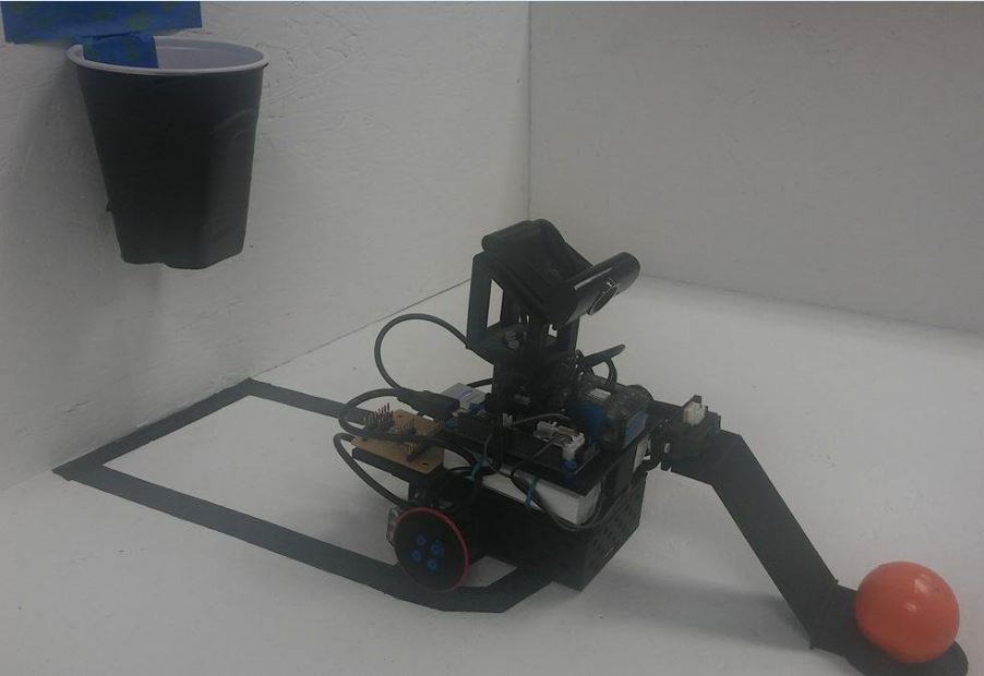
The objective of this project was to build a robot that could shoot a ball into a hoop, rebound the shot, and shoot the ball agiain autonomously.
System Architecture
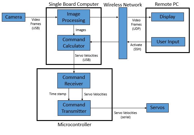
The architecture consists of a camera that feeds in frames into a single board computer (SBC) from a webcam via USB. The SBC filters the frame based on the desired tracking color. The filtered result is an array of 1's and 0's dictating where there is a match with the desired color and image. After averaging the 1's, the average position, relative to the camera frame, is determined and fed into the PID control loop. The PID control loop calculates the necessary rotational velocities of the left and right servos using the distance and position of the object from the center of the camera frame. The SBC sends theses movement commands to the microcontroller which commands the left and right wheels of the robot to servo onto either the backboard or ball.
Software Flowcharts
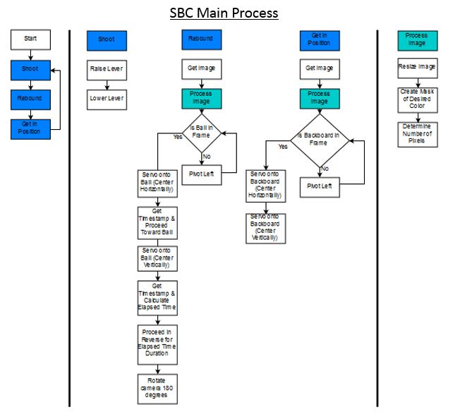
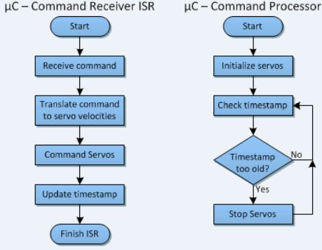
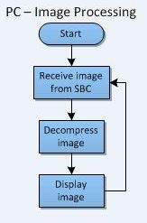
These are the flow charts that illustrate the behavior of software algorithms implemented on the SBC, the microcontroller, and the remote PC.
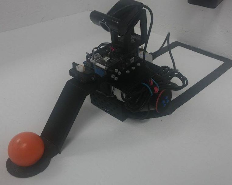
Physical Design
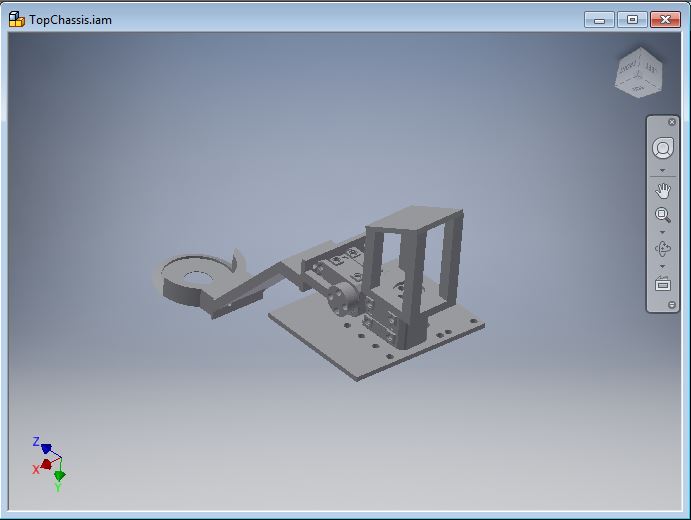
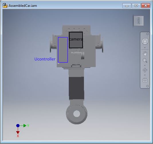
The structure of the car was designed using AUTODESK Inventor. There are two main components, the top chassis and the bottom chassis, which are separated and linked by the batteries. The robot was designed to be compact and to have a low center of gravity with an axis of rotation in the middle of the robot (excluding the shooting arm).
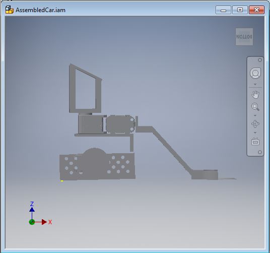
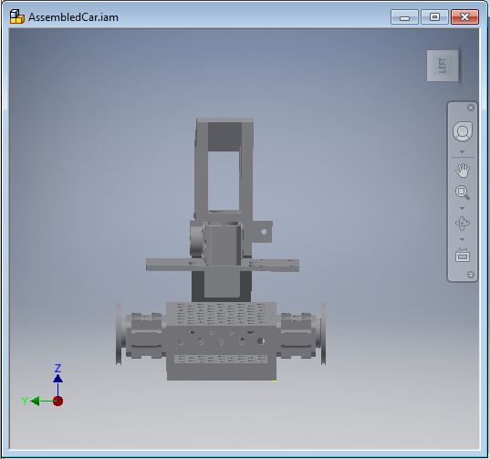
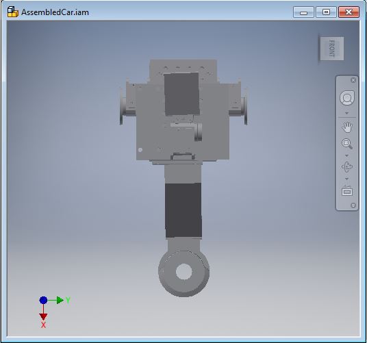
The top chassis houses the microcontroller, camera, and two servos. One so that it can track the rebound and then rotate to track the backboaard, and the other to rotate the shooting arm.
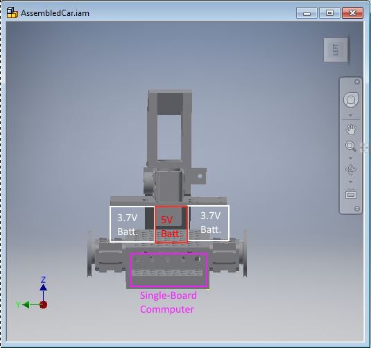
The bottom chassis houses the single board computer and the wheels. The casing of the SBC was designed to have the servos and batteries attach directly to the case
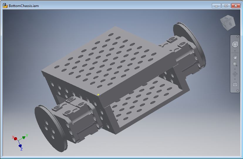
The following images outline the layout where the batteries, OpenCM microcontroller, single-board computer, and camera will reside.
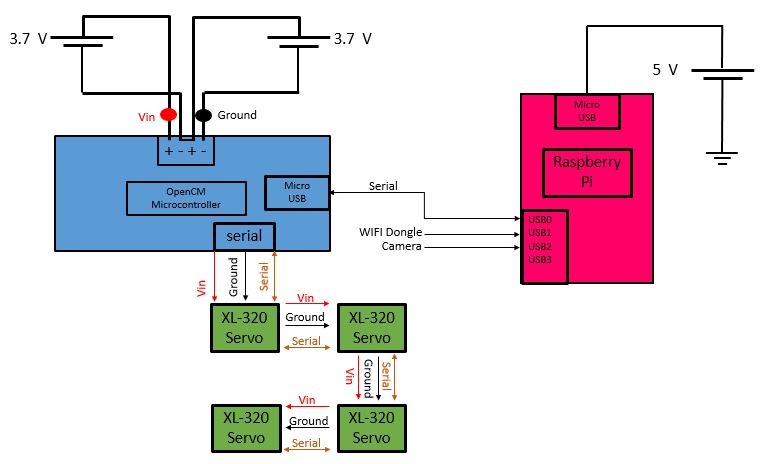
Electrical Design
Below is the diagram outlining the connections of the electrical components of the system. The Raspberry Pi is powered by an external 5V source. A wifi dongle and camera will be inputs to the Pi. A bidirectional connection will be established between the OpenCM microcontroller and the Pi via USB. The XL-320's will receive power, ground, and serial data from the microcontroller. The microcontroller will be powered by two external 3.7V batteries.