This was a collaborative effort with my fellow students. Please visit their pages as well:
Wes Tarro:http://mason.gmu.edu/~wtarro/ece-499/demo3/
David Hatch:http://mason.gmu.edu/~dhatch2/
This project was based on collaboration between robots. Our team dsigned, built, and implemented two robots, an autonomous crane and a remotely controlled hexapod. The hexapod needed to navigate the course and gather blocks and put them into the range of the crane. The hexapod then needed to activate a switch to turn the crane on to grab the block and place it within the middle.
System Architectures
Autonomous Crane
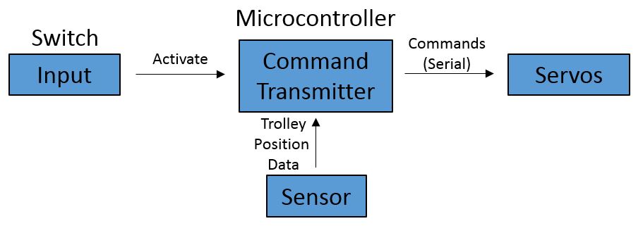
The architecture for the crane consisted of a switch to activate the crane. The microcontroller noted when the switch was hit and commanded the servos on the crane to act based on the feedback from the supersonic distane sensor.
Anty the Walking Hexapod
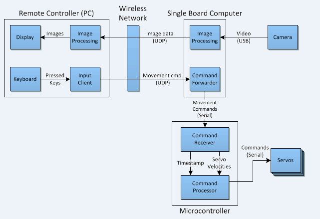
Our architecture for Anty is similar to that of our first project, the robotic car. It consists of a remote controller which feeds in movement commands to the single board computer over a wireless network. The single board computer sends the commands to the microcontroller via USB to control the servos. To localize the robot, a camera was attached to the single board computer, and then fed back the video frames to the remote controlling PC.
Software Flowcharts
Autonomous Crane
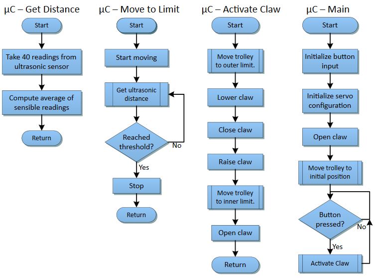
These are the flowcharts that describe the functionality of the program running on the microcontroller. The programs begins by intializing the servos, switch and ultrasonic sensor. When the switch is hit the claw is activated and moved out along the beam of the crane. The ultrasonic sensor determines the position of the claw along the beam by averaging a given number of sensible readings.
Anty the Walking Hexapod
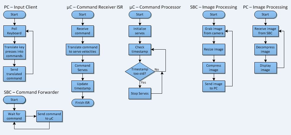
This diagram outlines the software implemented for the control of Anty.
Physical Design
Autonomous Crane
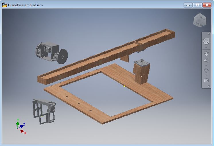
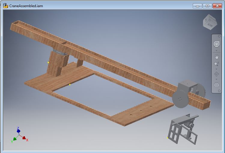
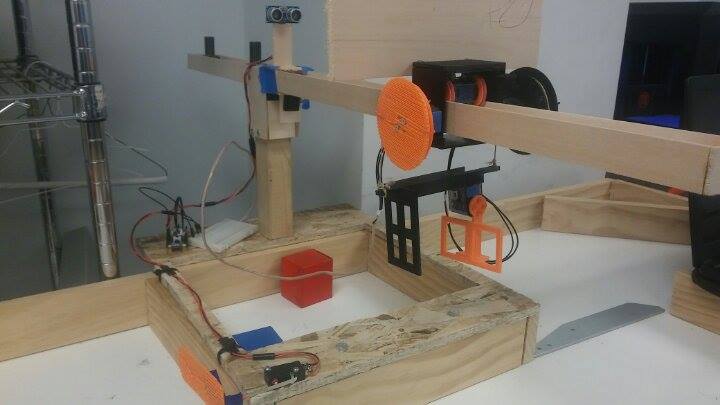
The structure of the crane was designed using AUTODESK Inventor. There are four main components of the design: The base-shaft, boom, trolley, and gripper.
1. The Base-Shaft
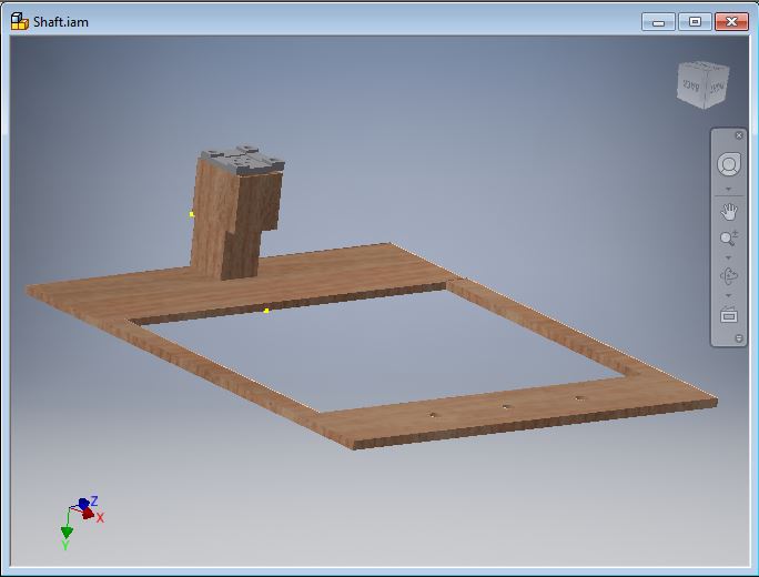
The base and shaft were primarily constructed of scrap wood found in the machining lab at GMU. There are three holes in the front of the base to mount the crane to the demonstration table. Mounted on top of a stationary XL-320 is a 3D printed piece that serves as the female end connector to link shaft with the boom. The outline of this 3D piece is supported by thin but supportive pieces of basswood. This minimizes the load on the horn caused by the boom.
2. The Boom

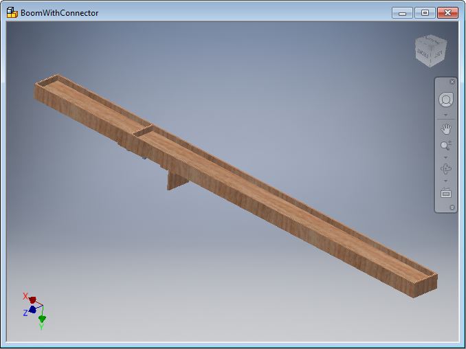
The boom was constructed of basswood since it is light weight and can provide an ample amount of support to satisfy the needs of the crane. On the bottom of the crane, there is the 3D printed male end connector to link the boom and the base-shaft.
3. The Trolley
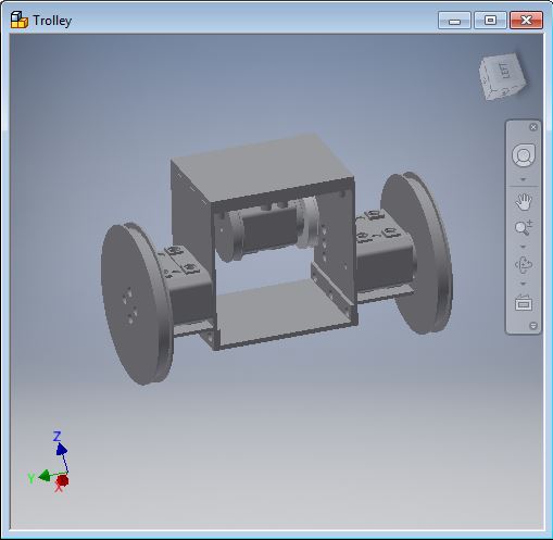
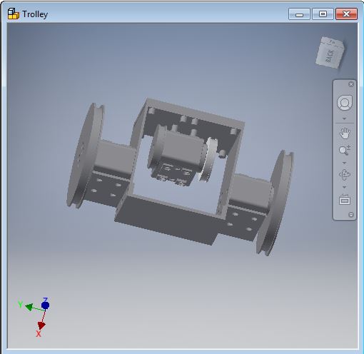
The trolley uses a chassis that was built from four 3D printed parts. There is a left and right plate. Connecting these two plates is a single Dynamel in the middle of the two plates. Attached to this Dynamixel are two wheels, one attached directly to the horn and the other attached via a screw on the backend. This Dynamixel is used to navigate the trolley along the boom. The two dynamixels on the outside have wheels attached to them. These wheels have strings attached to them which move the gripper up and down. To Provide additionaly stability to the chassis, a bottom and top plate was 3D printed and connected to the left and right plates.
4. The Gripper
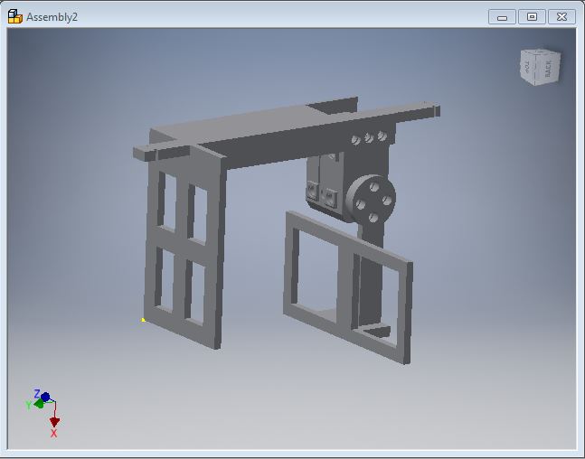
The gripper consists of a stationary plate, rotational arm, a Dynamixel servo and a leveling bar. The stationary plate and rotational arm are both connected to the Dynamixel. The length of the gripper needed be as along as the displacement between the two pulleys that were pulling it up and down, otherwise the string would roll of the pulley tracks.
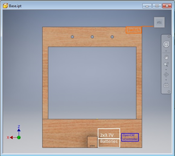
The following images outline the layout where the batteries, OpenCM microcontroller, switch, and ultrasonic sensor reside.

Anty the Walking Hexapod
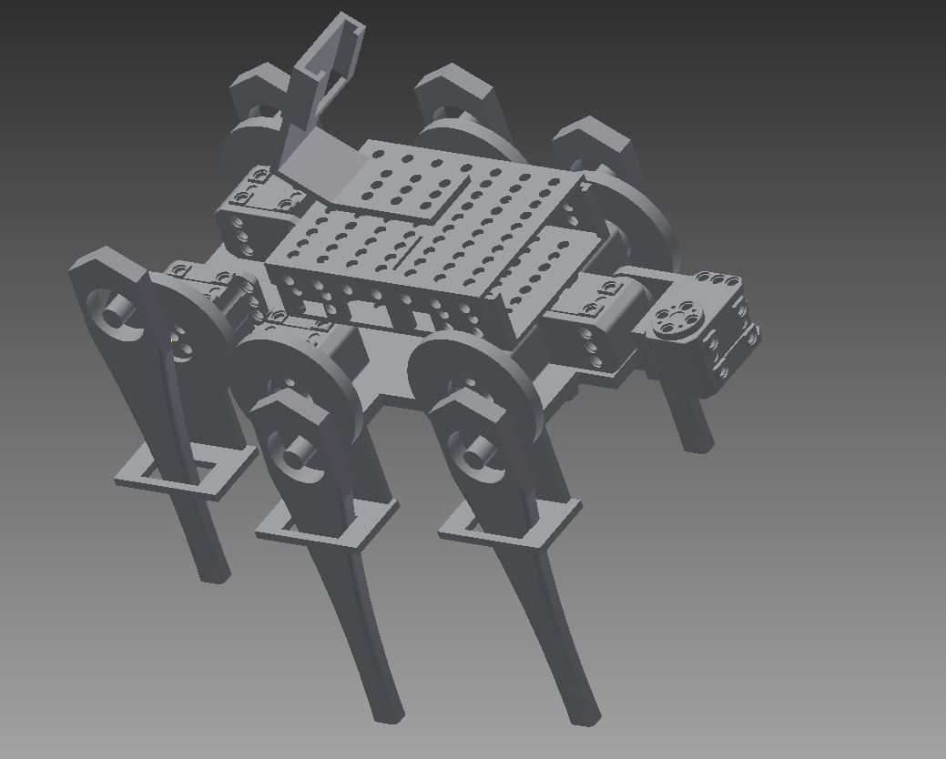
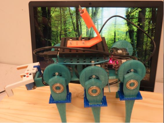
Above is the 3D model of our walker made in AUTOCAD. The chassis connects to seven servos, six for each leg, and one to connect the claw. The legs are attached to a bearing and the bearing is attached to a wheel on the servo. The chassis has built-in guides for the legs to ensure they travel in a linear motion, thus converting rotational motion from the servo into linear motion. The single-board computer is housed in the rectangular case shown on the chassis. The camera is attached to the case. At the front of the robot are the two servos used to control the claw.
Electrical Design
Autonomous Crane
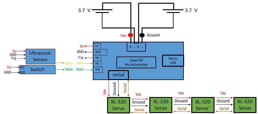
Below is the diagram outlining the connections of the electrical components of the crane. The switch and ultrasonic sensor are fed power from the microcontroller. The ultrasonic sensor is triggered by the microcontroller and then the sensor echos back a signal, relaying the distance. The state of the switch is connected to a GPIO pin on the microcontroller. The microcontroller is powered by 2 3.7V batteries in series. The microcontroller powers and feeds command signals into each of the servos.
Anty the Walking Hexapod
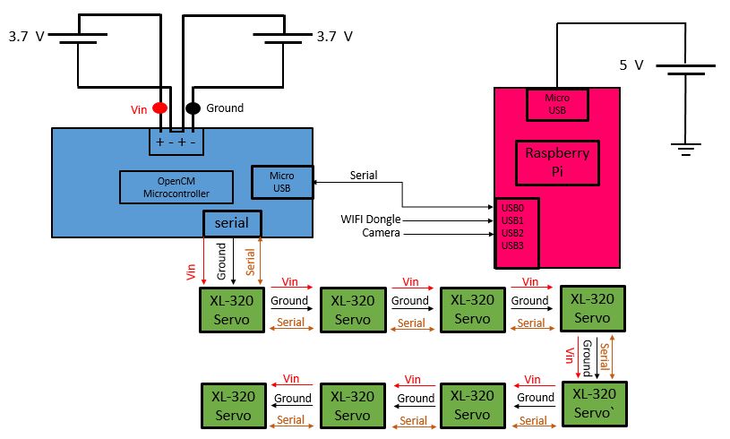
Below is the diagram outlining the connections of the electrical components of the walker. The Raspberry Pi is powered by an external 5V source. A wifi dongle and camera are inputs to the Pi. A bidirectional connection is established between the OpenCM microcontroller and the Pi via USB. The XL-320's will receive power, ground, and serial data from the microcontroller. The microcontroller will be powered by two external 3.7V batteries connected in series.
All programs, design files, and images can be found on Github at: https://github.com/michaelekepler/GMU-ECE590/tree/master/Project%203>
The architecture for the crane consisted of a switch to activate the crane. The microcontroller noted when the switch was hit and commanded the servos on the crane to act based on the feedback from the supersonic distane sensor.
Anty the Walking Hexapod
Our architecture for Anty is similar to that of our first project, the robotic car. It consists of a remote controller which feeds in movement commands to the single board computer over a wireless network. The single board computer sends the commands to the microcontroller via USB to control the servos. To localize the robot, a camera was attached to the single board computer, and then fed back the video frames to the remote controlling PC.
Software Flowcharts
Autonomous Crane
These are the flowcharts that describe the functionality of the program running on the microcontroller. The programs begins by intializing the servos, switch and ultrasonic sensor. When the switch is hit the claw is activated and moved out along the beam of the crane. The ultrasonic sensor determines the position of the claw along the beam by averaging a given number of sensible readings.
Anty the Walking Hexapod
This diagram outlines the software implemented for the control of Anty.
Physical Design
Autonomous Crane
The structure of the crane was designed using AUTODESK Inventor. There are four main components of the design: The base-shaft, boom, trolley, and gripper.
1. The Base-Shaft
The base and shaft were primarily constructed of scrap wood found in the machining lab at GMU. There are three holes in the front of the base to mount the crane to the demonstration table. Mounted on top of a stationary XL-320 is a 3D printed piece that serves as the female end connector to link shaft with the boom. The outline of this 3D piece is supported by thin but supportive pieces of basswood. This minimizes the load on the horn caused by the boom.
2. The Boom
The boom was constructed of basswood since it is light weight and can provide an ample amount of support to satisfy the needs of the crane. On the bottom of the crane, there is the 3D printed male end connector to link the boom and the base-shaft.
3. The Trolley
The trolley uses a chassis that was built from four 3D printed parts. There is a left and right plate. Connecting these two plates is a single Dynamel in the middle of the two plates. Attached to this Dynamixel are two wheels, one attached directly to the horn and the other attached via a screw on the backend. This Dynamixel is used to navigate the trolley along the boom. The two dynamixels on the outside have wheels attached to them. These wheels have strings attached to them which move the gripper up and down. To Provide additionaly stability to the chassis, a bottom and top plate was 3D printed and connected to the left and right plates.
4. The Gripper
The gripper consists of a stationary plate, rotational arm, a Dynamixel servo and a leveling bar. The stationary plate and rotational arm are both connected to the Dynamixel. The length of the gripper needed be as along as the displacement between the two pulleys that were pulling it up and down, otherwise the string would roll of the pulley tracks.
The following images outline the layout where the batteries, OpenCM microcontroller, switch, and ultrasonic sensor reside.
Anty the Walking Hexapod
Above is the 3D model of our walker made in AUTOCAD. The chassis connects to seven servos, six for each leg, and one to connect the claw. The legs are attached to a bearing and the bearing is attached to a wheel on the servo. The chassis has built-in guides for the legs to ensure they travel in a linear motion, thus converting rotational motion from the servo into linear motion. The single-board computer is housed in the rectangular case shown on the chassis. The camera is attached to the case. At the front of the robot are the two servos used to control the claw.
Electrical Design
Autonomous Crane
Below is the diagram outlining the connections of the electrical components of the crane. The switch and ultrasonic sensor are fed power from the microcontroller. The ultrasonic sensor is triggered by the microcontroller and then the sensor echos back a signal, relaying the distance. The state of the switch is connected to a GPIO pin on the microcontroller. The microcontroller is powered by 2 3.7V batteries in series. The microcontroller powers and feeds command signals into each of the servos.
Anty the Walking Hexapod
Below is the diagram outlining the connections of the electrical components of the walker. The Raspberry Pi is powered by an external 5V source. A wifi dongle and camera are inputs to the Pi. A bidirectional connection is established between the OpenCM microcontroller and the Pi via USB. The XL-320's will receive power, ground, and serial data from the microcontroller. The microcontroller will be powered by two external 3.7V batteries connected in series.
All programs, design files, and images can be found on Github at: https://github.com/michaelekepler/GMU-ECE590/tree/master/Project%203>