Remotely Monitored & Controlled Crane
This was a collaborative effort with my fellow student Wes Tarro. Please visit his page at:http://mason.gmu.edu/~wtarro/ece-499/demo2/
System Architecture
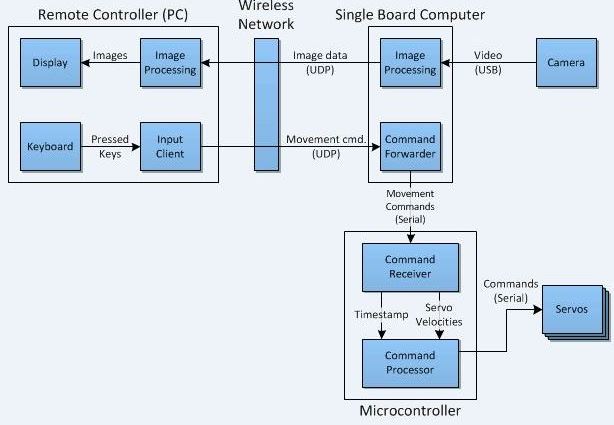
Our architecture is similar to that of our first project, the robotic car. It consists of a remote controller which will feed in movement commands to the single board computer over a wireless network. The single board computer will send the commands to the microcontroller to control the servos. To localize the robot, a camera will be attached to the single board computer, and it will then feed back the video frame to the remote controlling PC.
Software Flowcharts
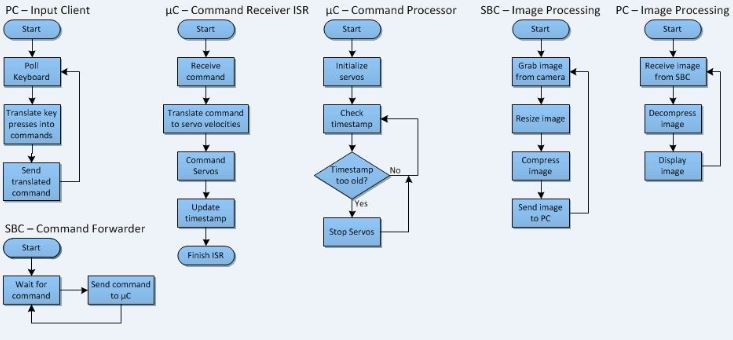
These are the flow charts that illustrate the behavior of our software algorithms implemented on the remote PC, the single board computer, and the microcontroller.
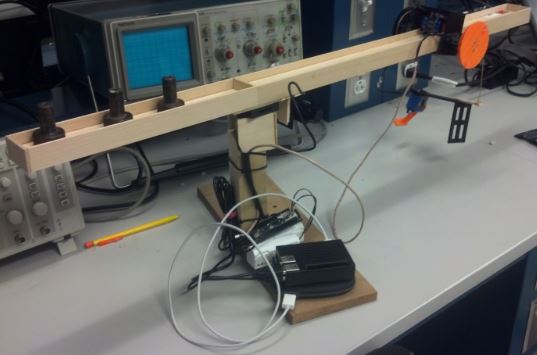
Physical Design
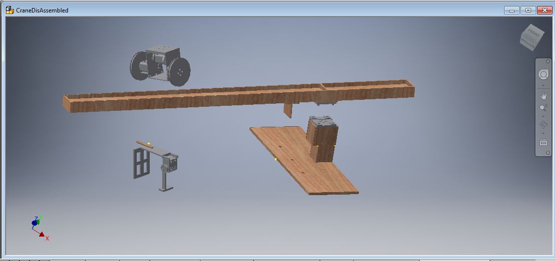
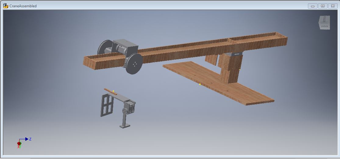
The structure of the crane was designed using AUTODESK Inventor. There are four main components of the design: The base-shaft, boom, trolley, and gripper.
1. The Base-Shaft
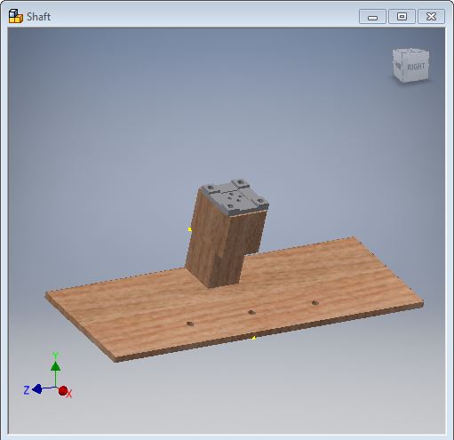
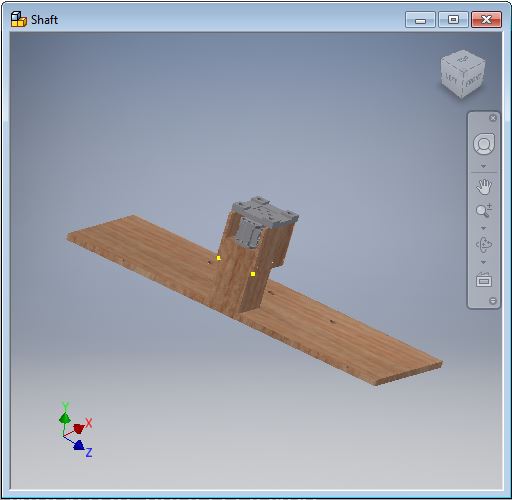
The base and shaft were primarily constructed of scrap wood found in the machining lab at GMU. There are three holes in the front of the base to mount the crane to the demonstration table. The servo was mounted to the shaft via three screws through the backend of the XL-320. Mounted on top of the XL-320 is a 3D printed piece that serves female end connector to link shaft with the rotating boom. The outline of this 3D rotational piece is supported by thin but supportive pieces of basswood. This minimizes the load on the horn caused by the boom.
2. The Boom

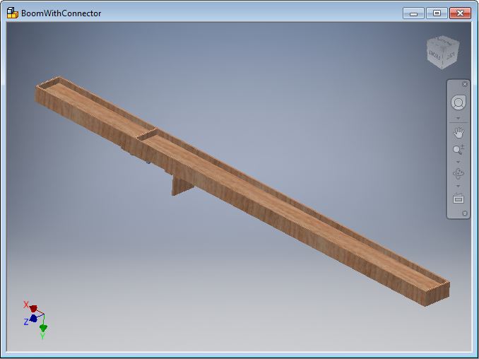
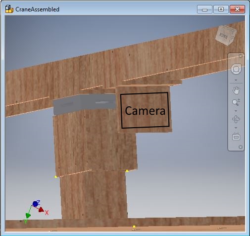
The boom was constructed of basswood since it is light weight and can provide an ample amount of support to satisfy the needs of the crane. On the bottom of the crane, there is the 3D printed male end connector to link the boom and the base-shaft. Perpendicular to the boom, is a vertical piece of basswood used to mount the camera via velcro strips. On top of the boom there are two divisions. One half is a track for the trolley to navigate along the boom. The other half is used as an area for counter weights to neutralize the load on the servo that rotates the boom. To determine the proper counterweight load, the trolley was placed in the middle along the navigational tracks and then counterweights were added until the boom reached its quiescent point.
3. The Trolley
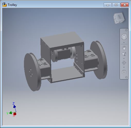
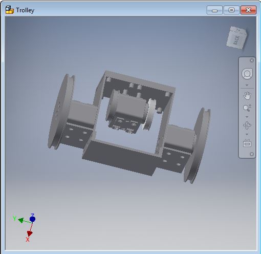
The trolley uses a chassis that was built from four 3D printed parts. There is a left and right plate. Connecting these two plates is a single Dynamel in the middle of the two plates. Attached to this Dynamixel are two wheels, one attached directly to the horn and the other attached via a screw on the backend. This Dynamixel is used to navigate the trolley along the boom. The two dynamixels on the outside have wheels attached to them. These wheels have strings attached to them which move the gripper up and down. To Provide additionaly stability to the chassis, a bottom and top plate was 3D printed and connected to the left and right plates.
4. The Gripper
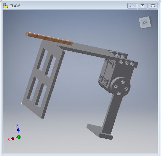
The gripper consists of a stationary plate, rotational arm, a Dynamixel servo and a leveling bar. The stationary plate and rotational arm are bothe connected to the Dynamixel. The leveling bar is attached to the stationary plate. This bar was not part of the initial design and had to be added. After doing some initial testing, we noticed that the length of the gripper need be as along as the displacement between the two pulleys that were pulling it up and down, otherwise the string would roll of the pulley tracks. Had we taken this into account intially, we would have 3D printed this part rather than used a piece of basswood.
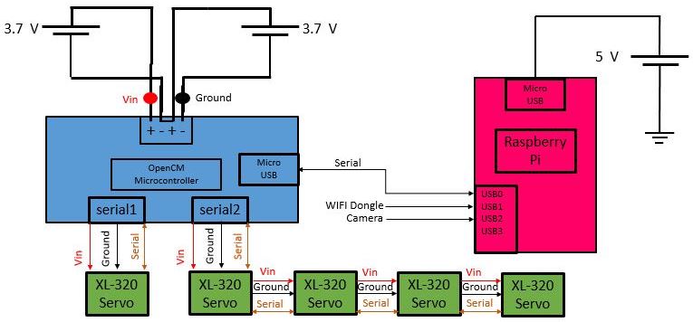
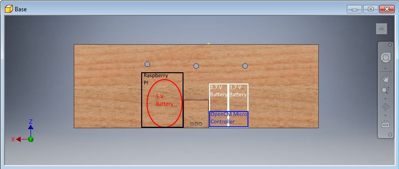
The following images outline the layout where the batteries, OpenCM microcontroller, Raspberry PI, and camera will reside.
Electrical Design
Below is the diagram outlining the connections of the electrical components of the system. The Raspberry Pi is powered by an external 5V source. A wifi dongle and camera will be inputs to the Pi. A bidirectional connection will be established between the OpenCM microcontroller and the Pi via USB. The XL-320's will receive power, ground, and serial data from the microcontroller. The microcontroller will be powered by two external 3.7V batteries.