Color Tracking with Computer Vision
This was a collaborative effort with my fellow student Wes Tarro. Please visit his page at:http://mason.gmu.edu/~wtarro/ece-499/hw5/
The objective of this assignment was to use the car that was built in the first project to 'servo' onto a block of a specified color, i.e. using OpenCV have the car rotate until it sees the block of the desired color and then track the block as it moves.
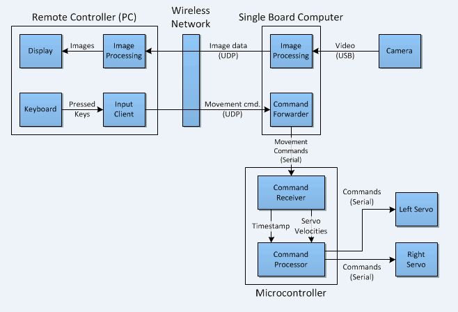
System Architecture
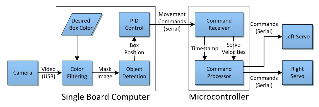
Our architecture consists of a camera that feeds in frames into a single board computer (SBC) from a webcam via USB. The SBC filters the frame based on the desired tracking color. The filtered result is an array of 1's and 0's dictating where there is a match with the desired color and image. After averaging the 1's the average position, relative to the camera frame, is determined and fed into the PID control loop. The PID control loop calculates the necessary rotational velocities of the left and right servos using the distance and position of the object from the center of the camera frame. The SBC sends theses movement commands to the microcontroller which commands the left and right wheels of the robot to servo onto to the block of the desired color.
Software Flowcharts
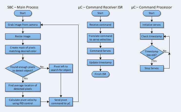
These are the flow charts that illustrate the behavior of software algorithms implemented on the SBC and the microcontroller.
Physical Design
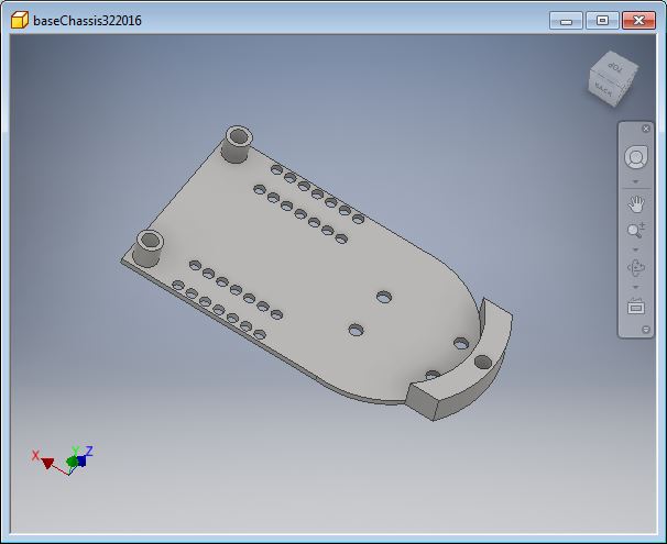
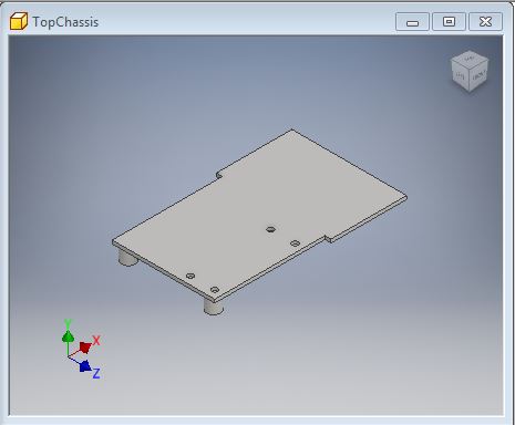
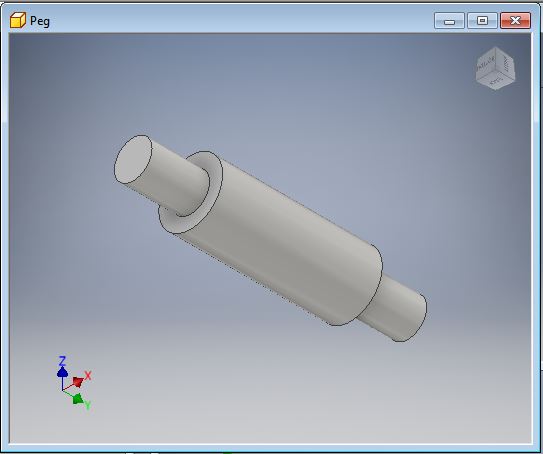
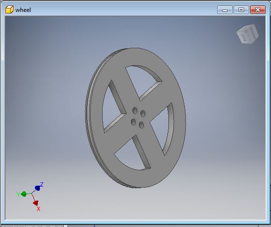
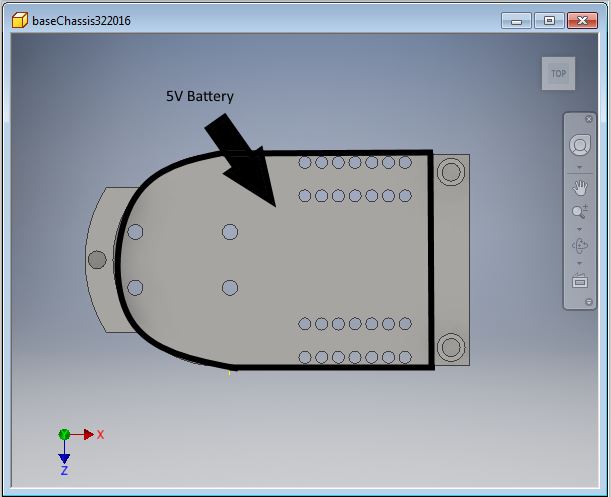
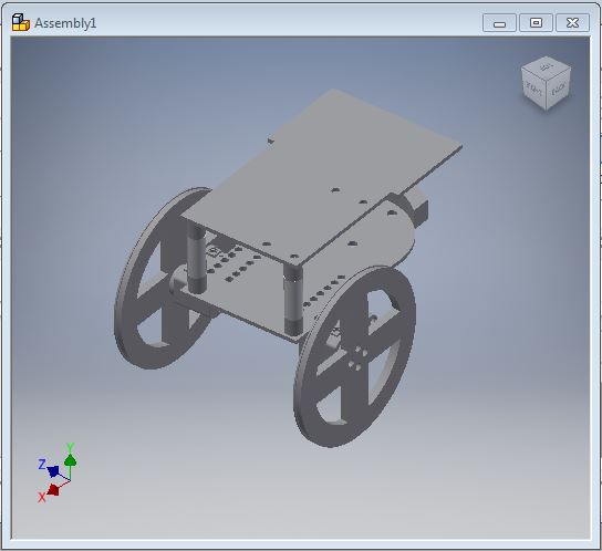
The structure of the car was designed using AUTODESK Inventor. Here are the four main components of the design: The base chassis, the top chassis, the connecting pegs, and the wheels. The physical design differs from the one used in project 1. We moved the wheels in closer to the center of gravity to enable smoother turns with less slippage.
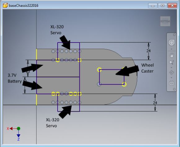
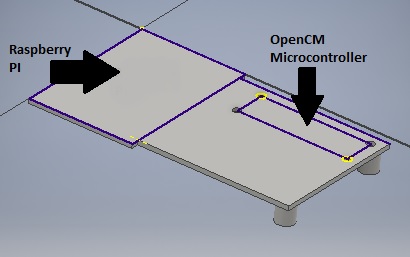
The following images outline the layout where the batteries, XL-320's, wheel caster OpenCM microcontroller, Raspberry PI, and camera will reside.
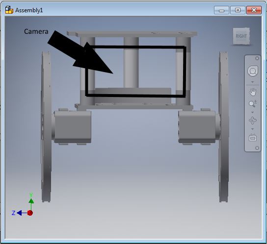
Lastly is the image of the assembly of the 3D printed parts that make up the car. (not pictured is the single wheel caster in the back of the vehicle)
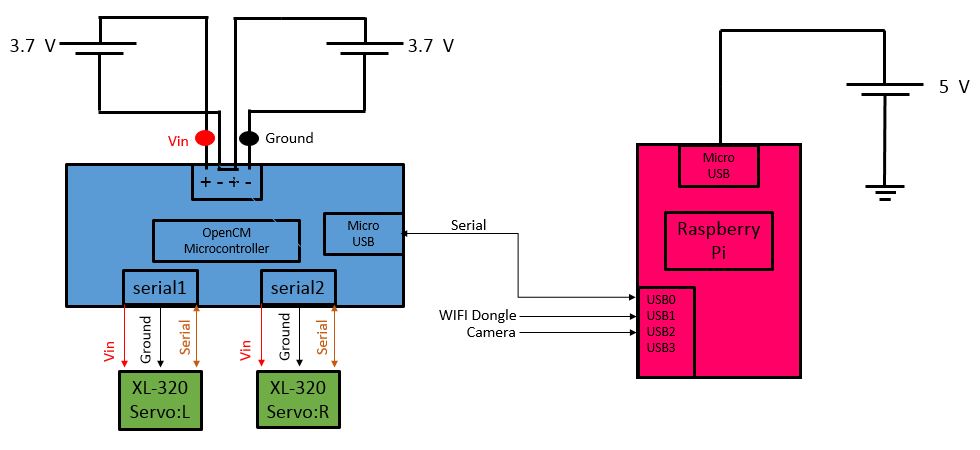
Electrical Design
Below is the diagram outlining the connections of the electrical components of the system. The Raspberry Pi is powered by an external 5V source. A wifi dongle and camera will be inputs to the Pi. A bidirectional connection will be established between the OpenCM microcontroller and the Pi via USB. The XL-320's will receive power, ground, and serial data from the microcontroller. The microcontroller will be powered by two external 3.7V batteries.