Heat Distribution on a Cooling Fin
This project is being done jointly by Anna-Rose Wolff, Donnelly Phillips, and Dylan Kilpatrick.
This project modeled the steady-state distribution along a rectangular fin of a heat sink. We modeled the heat energy entering the fin along part of one side. The fin shape is a thin, rectangular slab with dimensions \(L_x \times L_y \) and a width of \( \delta \) centimeters, where \( \delta \) is small. Because of the thiness of the slab, the temperature is considered to be constant along the width dimension. The distribution of heat along the fan can be modeled with partial differential equations. These partial differential equations are then solved usin the Finite Difference Method.
The following constants are important in the final differential equations. Each type of material has a constant of thermal conductivity, denoted \( K \). \( H \) is a proportionality constant called the convective heat transfer coefficient and \(u_b \) is the ambient temperature of the surrounding fluid. The step sized used in solving the partial differential equation is denoted by M and N. For ease of solving, we set M=N for all of our solutions. The code to model, solve, and graph the partial differntial equations of the cooling fin can be found here
Power and Temperature in an Aluminum Fin
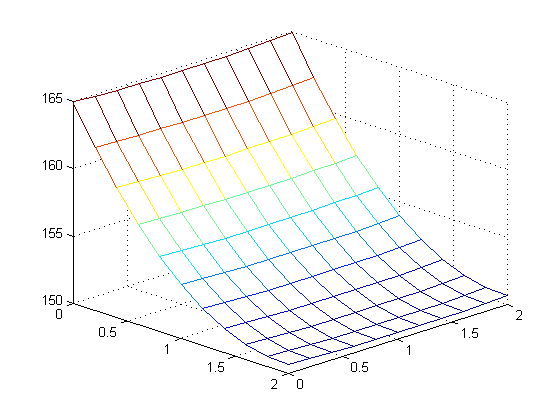
We began with a 2x2x.1 cm fin with a 5 watt power input along the entire left edge. Furthermore, we assumed that the fin was made of aluminum with a thermal conductivity of K = 1.68 Watts per centimeter-degrees Celsius, that the convective heat transfer coefficient was H = .005 Watts per centimeters squared-degrees Celsius, a that the ambient room temperature was 20 degrees Celsius. The partial differential equations associated with the cooling fin was solved with M=N=10. After plotting the heat distribution, the maximum temperature was found to be 164.9357 celsius. A plot of the heat distribution along the fin can be seen below.
Next, we increased the size of the fin to 4x4x.1 cm. 5 Watts of power was inputted
along 2 cm of the left edge, as before. The resulting distribution gave a maximum
temperature of 69.4704 Celsius for M=N=10.
Increasing the step size to M=N=20, the maximum temperature was found to be 70.9232 Celsius.
Increasing the step size to M=N=40, the maximum temperature was found to be 71.7310 Celsius.
Increasing the step size to M=N=80, the maximum temperature was found to be 72.1537 Celsius.
So the total change in the solution was 2.6833 degrees Celsius
The heat distribution for all four cases can be seen below.
 |
 |
| M=N=10 | M=N=20 |
 |
 |
| M=N=40 | M=N=80 |
We built a bisection method to find the max power that can be dissipated by a 4x4x.1 cm
fin while keeping the temperature below 80 degrees Celsius.
In order to properly run the bisection method, the inputs to our PDE function
and solver had to be changed. The bisection method and the new PDE function
can be found here
and here
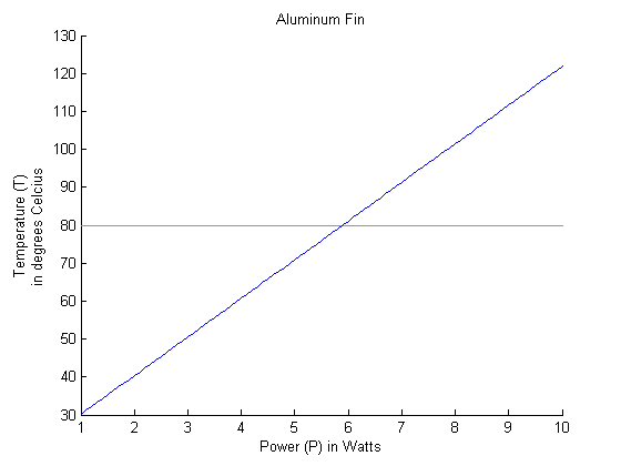
The bisection method returned a max power of 5.8912 Watts possible while keeping the fin under
80 degrees Celsius.
Below is a graph of the power dissipated by the fin versus the maximum temperature of the fin.
Power and Temperature in a Copper Fin
Using the same bisection method and PDEs as above, we changed the thermal conductivity of
the fin to reflect a copper fin, K = 3.85 Watts per centimeter-degrees Celsius. We found that the maximum power dissipated
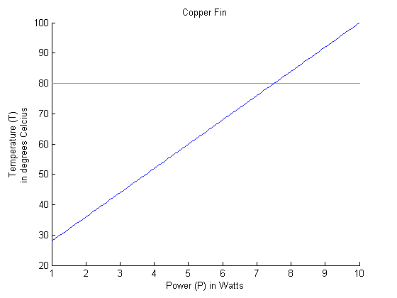
by a 4x4 cm fin while keeping the fin below 80 Celsius was found to be 7.5063 Watts.
Below is a graph of the power dissipated by the fin versus the maximum temperature of the fin.
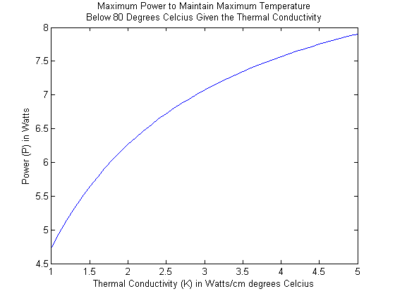
Next, we plotted the maximum power that can be dissipated by a 4x4 cm fin while keeping the maximum temperature below 80 Celsius as a function of thermal conductivity, for \( 1 \leq K \leq 5 \) Watts per centimeter-degrees Celsius. A function f was designed to take thermal conductivity as an input, and as its output would have the maximum power that can be used while experiencing temperatures below 80 degrees Celcius. As explained before, for a given thermal conductivity, a bisection method is used to find this maximum power. The code for graphing this function is here.
These two graphs below demonstrate that, for any thermal conductivity from 1 to 5, this maximum power lies between 1 and 5. Hence, when running the bisection method, 1 and 5 will suffice as boundary points. The results of the algorithm are below.
 |
 |
| Power versus maximum temperature dissipated for a fin with a thermal conductivity of 1. |
Power versus maximum temperature dissipated for a fin with a thermal conductivity of 5. |
Power and Temperature in a Water-Cooled Copper Fin
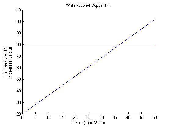
In step 6, we looked at a water-cooled 4x4 cm copper fin. We assumed that the water has a convective heat transfer coefficient of H = .1 Watts per centimeters squared-degrees Celsius and that the ambient water temperature was 20 degrees Celsius. Using the same bisection method as before, we determined that a maximum power of 36.7623 Watts can be dissipated while still keeping the fin below 80 degrees Celsius.
Notching a Copper Fin
Step 7 asked us to cut out a rectangular notch from the right side of the cooling fin and to repeat the analysis from step 4 (copper fin) to discover whether or not more or less power was dissipated. The idea was to allow input to the function with the dimensions of the notch and to shift the boundary layers accordingly. The code can be found here.
This created a problem. Despite seemingly clear logic, the altering of the matrix A rendered A\b unsolvable. We think that another approach might leave us a solvable system. Instead of leaving the notch blank in A, we would remove the rows that were entirely zero as well as their corresponding b index and solve that system. Unfortunately, we never got a chance to try it out. Who knows...