| GMU | CS Wiki |
|
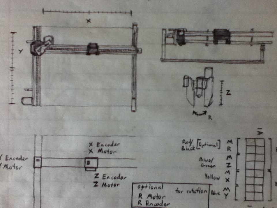
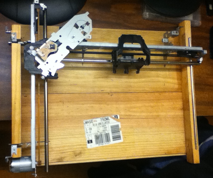
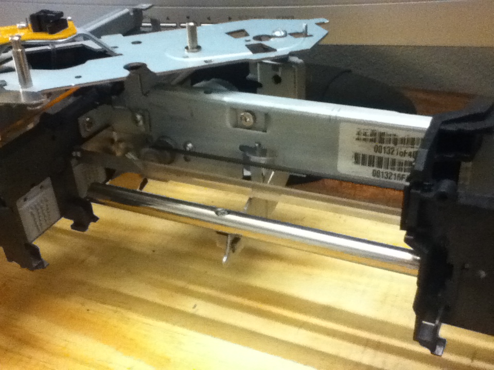
Building The Frame and Rails: Two broken HP Color-Jet printers were stripped down to salvagable parts and mounted on a plywood frame. Aluminum peices of the printers were crafted into brackets to hold both of the rails together. The opposite end of the horizontal carriage just stood freely on top of a mounted rail for reduced friction. Both rails were cut from printer frames while retaining the necessary components for moving the carriage head. The motors, drive band, and encoder strip remained part of the rails. 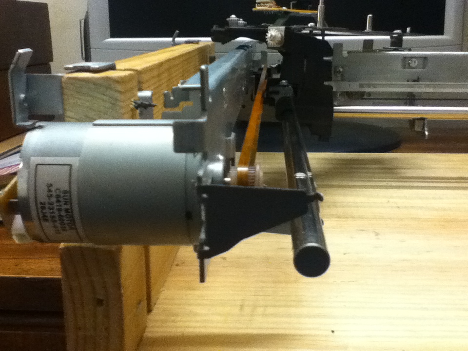
|
Electrical Designs:
|
|
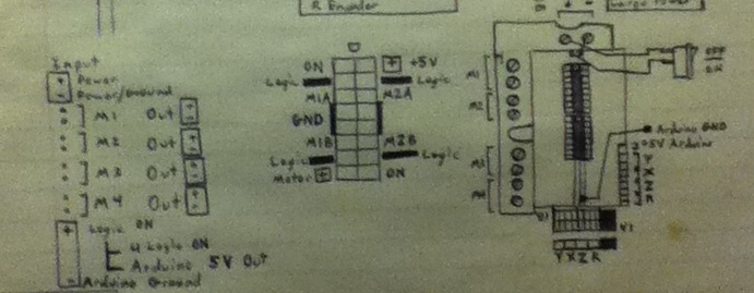
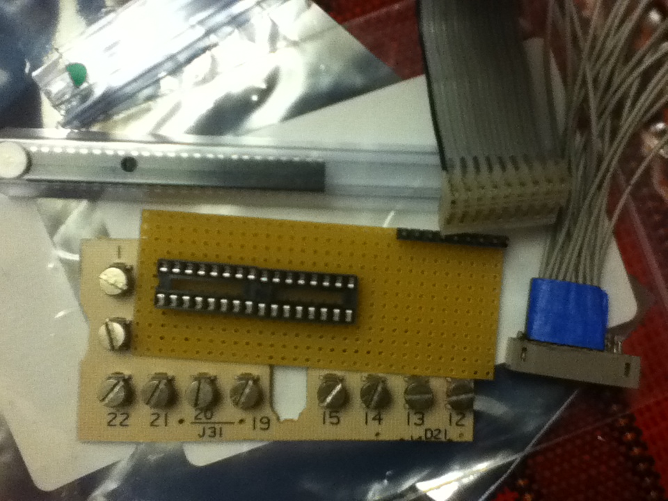
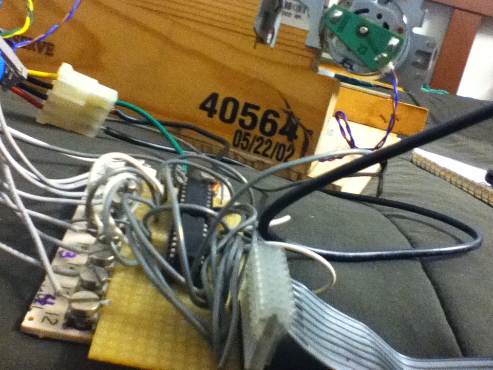
The Motor Controller: Initially an idea for the motor control was to re-use the printer circuit board to control the motors, but due to the proprietary implementation of the Integrated Circuit chips for control of abstracted printer functionality instead of direct motor control, a different path had to be decided. The secondary idea in mind was to build a multi H-bridge motor control circuit out of Mosfet transistors on a solderable bread board. The cost of four Mosfets per motor evaluated to be too high, and unnecessary for the small amperage load of the carriage motors. The idea was redesigned to instead use cheaper, quad-Half-Bridge ICs with a lower amperage tolerance in order to compensate for the price by only costing $2 per IC, two of which could drive four motors in any direction. Later on after further testing, resistance on the motors from drag and weight raised the amperage load to higher levels, and at one instance, burned out a chip and the two pins on the microcontroller. Due to this design failure, the quad-Half-Bridge ICs were double stacked to increase the current tolerance for the two carriage motors, and a heat sink was added to dissapate the heat generated from current overdraw. This updated design has solved the past problems. |
|
|
The IR Encoders: Multiple IR encoders were salvaged from the printers. The sensors were used for detecting paper entrance, tracking feed motor movement, and carriage movement. The carriage movement encoders were coupled on a circuit board along with functions of controlling the ink flow. The complexity of the incoming pins to the specialized circuit board lead me to consider a combination of the other IR encoders for reading the carriage movement. Simpler 2-way encoders from the paper feed were the first things that came to mind. They were already coupled with a wire connector with four pins for directly supplying power and reading the status of the two IR sensors inside. After testing the encoders mounted on the carriages, the sensor passing between a line and a space triggered a counter on a simple script and recorded the number of lines passed on a single run from one side to the other. The numbers came out different for each trial. From further experimentation, I came to the conclusion that the spacing between the two IR sensors of the paper feed encoder was different from the spacing between the sensors of the carriage encoder, thus the very miniature lines of the encoder strip were getting skipped. I then decided to create my own encoder strips to lower the resolution, but allow compatibility with the new encoders. I created a graphical image with precisely spaced black and white pixels of different spacings to print onto a transparency at the local printing store for a few cents. 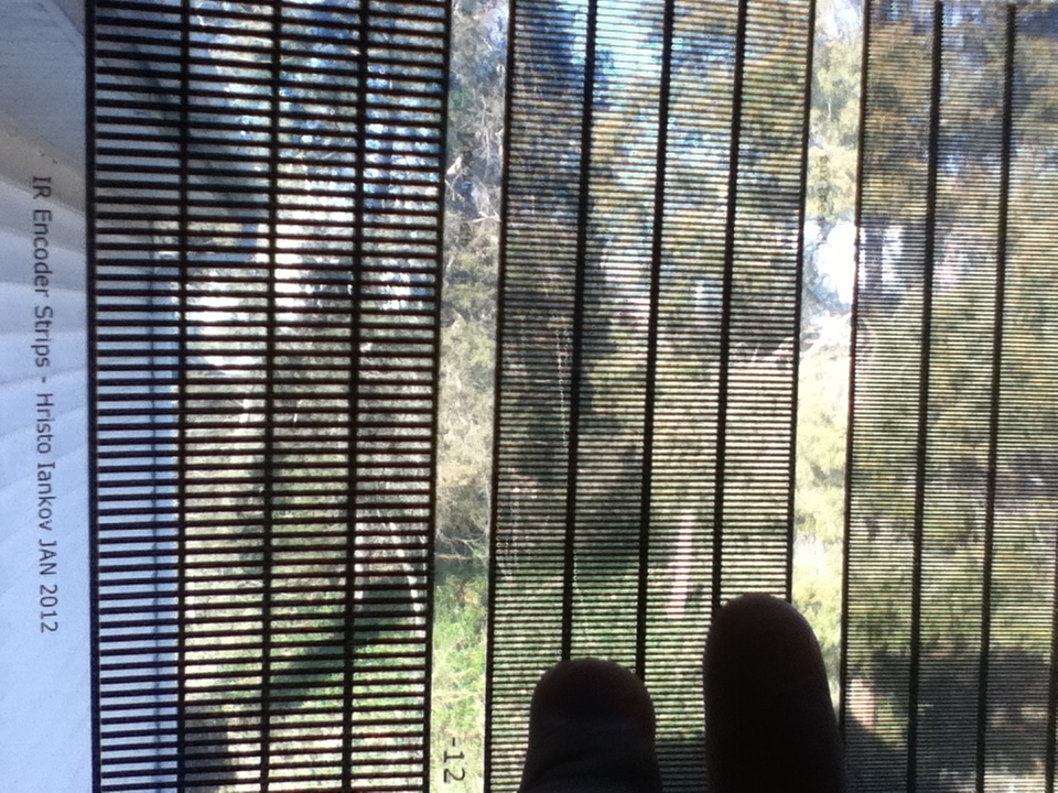
The plan worked better than I had anticipated, and one of the particular spacings worked perfectly with the new encoders. The script would return the same counter number for each trial. |
Software Designs:
|
Microcontroller Interface: An Arduino UNO microcontroller was used to read sensor data and control motor movement of the machine. The raw incoming information was converted to usable positioning data and accurate speed control of the motors. Port communication to the computer was written with abstracted commands for controlling the printer. In this model, the higher priority computations were done on the motor controller, while data that could afford to be read at a slower rate was passed over serial port to a computer. |
|
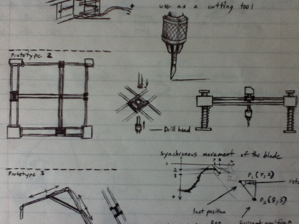
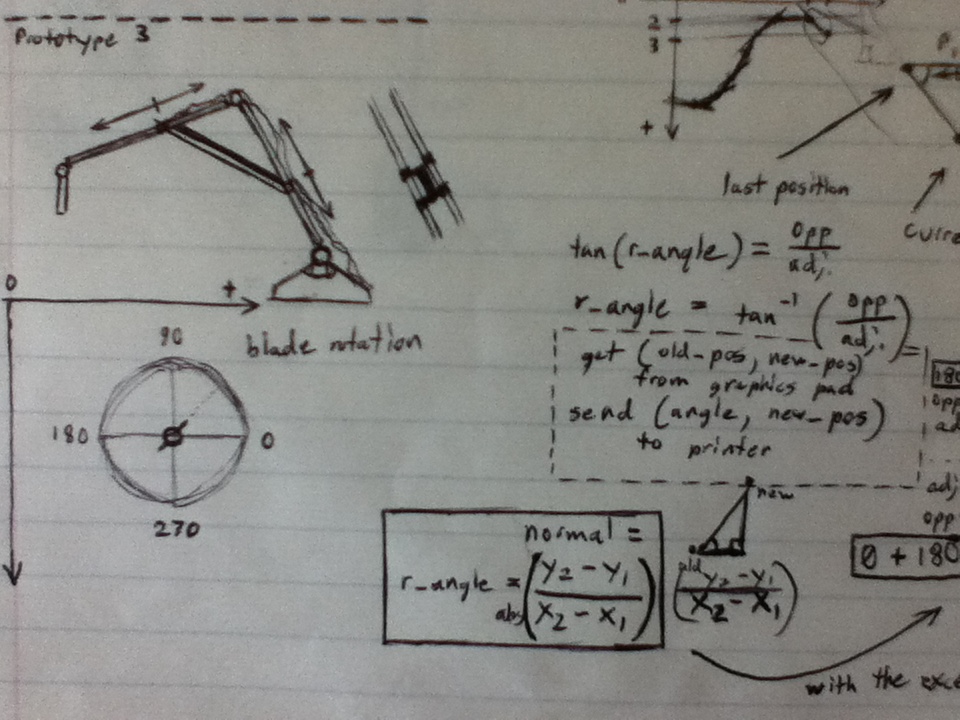
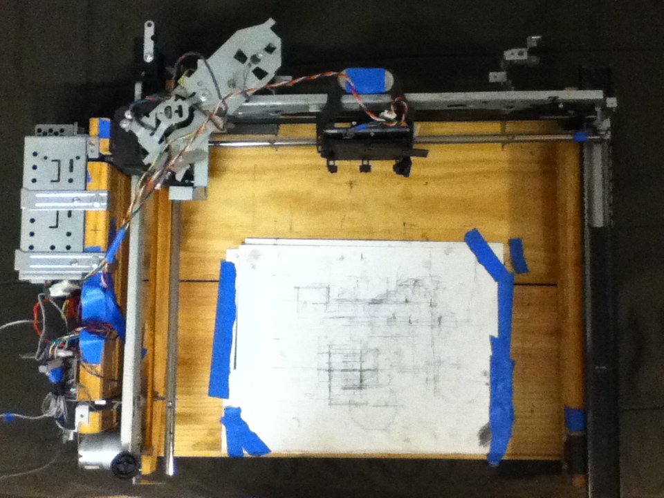
User Interface A user interface was designed for controlling the machine through established PC input devices. The interface could then communicate the user's intentions to the micocontroller which would in turn pass information to control the motors. The keyboard was implemented as a way of debugging through interrupt movement commands by the arrow keys, and shortcut path saving and reprinting. The mouse was implemented as a way of drawing paths for the carriage to follow through a queue of points formulating those paths. These paths could be sketched as easily as holding down the right mouse button and drawing. The left mouse button was used for interrupt movement to a specified point on the coordinate system. 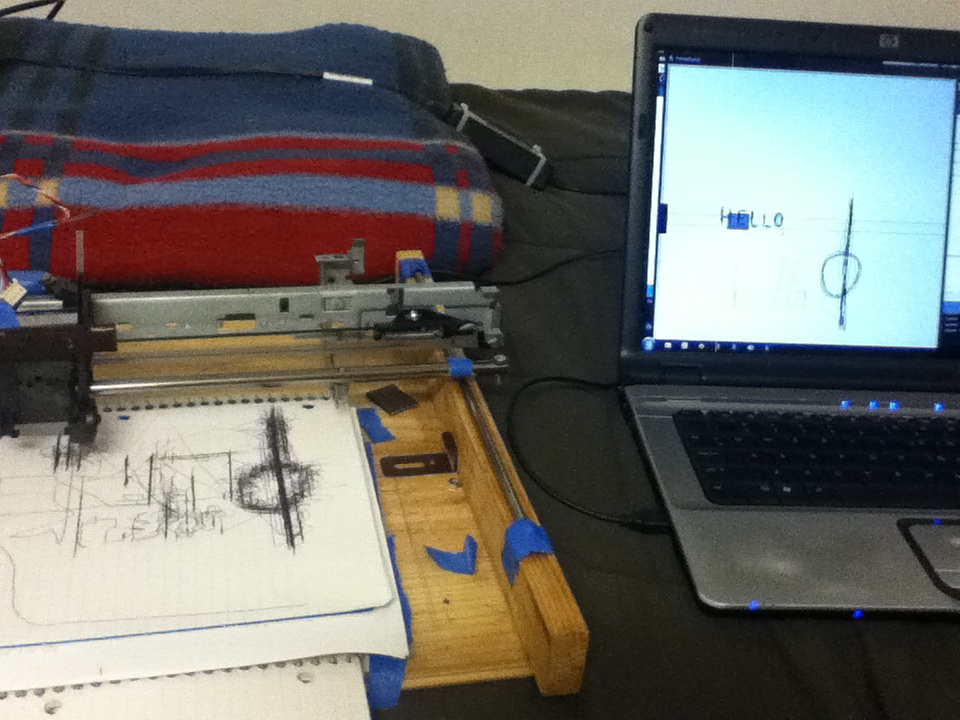 (image on right drawn by mouse on PC Interface, and print machine on left is re-drawing the same paths with an attached pen) The interface itself, displayed the positions of the rails and carriage on the coordinate system in real-time. During movement testing, the carriages would skip over their next specified (X,Y,Z) coordinate and vibrate at large speeds towards it from opposing directions. Lowering the movement speed of the motors alltogether through slower Pulse Width Modulation waves, fixed the problem of skipping over coordinates, but introduced an issue of not having enough motor power to push the rails at some locations. From those issues, smarter motion control algorithms had to be designed. A few ideas came to mind: Varried PWM Movement - Movement speed varriation based on the distance between the current position of the carriage to the desired coordinates. The further the current position from the target position, the higher speed setting on the motors. The closer to the target position, the slower the motors were set to move. These speeds were put on a treshold so as to not run too fast, or so slow that movement was impossible. The target coordinates were put on a treshold as well, for an acceptable range of having reached the coordinate, instead of having to park exactly on the specific pixel. Velocity Push - Movement varried by actual velocity of the motor and the power supplied to it. An actual value of carriage speed could be determined by logging carriage position over time. An estimated current velocity value could then be read at any time. This value could then be used to increase the PWM wave speed to the specific motor if it is not moving as it should be. This push would solve the problem from the end of having too low power to even move, but still retain the ability to move slowly at cloer target locations. |
Conclusions/Progress:
|
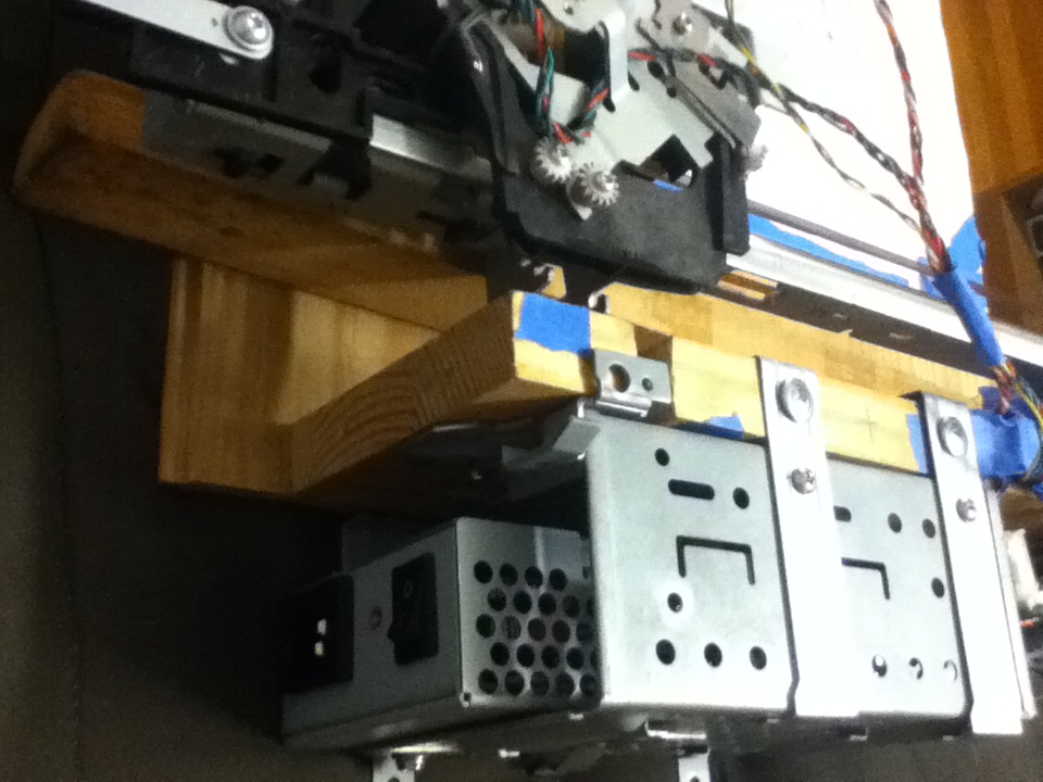
Continued Issues The horizontal rail, having not been secured on the right side to the side rail, creates a swing during all vertical printer movements. The swing becomes more significant with higher velocity to abrupt stops of movement. The right rail was reimplemented with a guiding rail of a metal cabinet drawer. The new guiding rail seems to experience increased drag during movement at rare times. Further redesigns have to be considered. Design Updates: - An on-board power-supply, salvaged from an old network switch, has been attached to the printer. - CD Laser head movement device has been salvaged to use as a linear actuator for the Z-axis movement. - Carriage holding the horizontal rail has been reinforced with an aluminum encasing created from scraps cut out of the original printers. 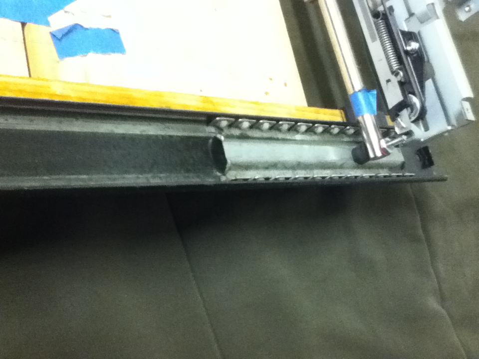 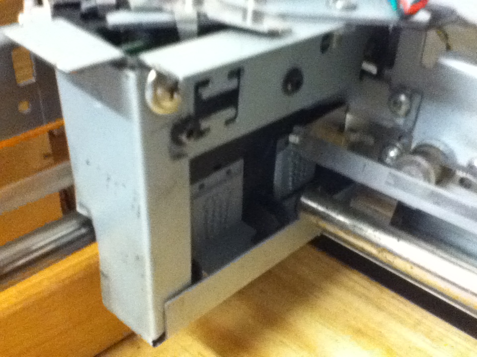
|
George Mason Computer Science Undergraduate Student Website -- Hristo Iankov 2011