Dr. Riki Morikawa, George Mason University
updated 27May2015
Baud Versus Bits per Second
Back to Index
When we think of the data throughput of a digital network, we typically think in terms of bits per second. A single data bit can represent one of two values, a logical "1" or "0". Since one bit of data can only represent one of two values, we describe this as binary data represented by "base 2" numbers. In comparison, "base 10" numbers (i.e., values between 0 and 9) are what we use every day.
A string or 8 or more bits can make up a byte or "data word" consisting of 1's and 0's. The order in which the 1's and 0's appear in the byte can then be encoded into a symbol such as "A", "B", "C", "9", "8", ":)", etc. Bytes mapped, or encoded, into symbols can follow several standards such as ASCII, EBCDIC, UNICODE, etc.
If we wish to transmit a sequence of logical data words via electrical signal, we need to "line code" our data word into an electrical signal. As an example, we may simply specify that a logical "1" is represented by 3 volts, and a logical "0" by 0 volts (figure 1). There are many line coding techniques such as Manchester, NRZ, AMI, B8Zs, which will be covered in your lecture slides.
In figure 1, each time we send a 3 volt pulse, the receiver translates this pulse as a logical "1". If on the other hand we send 0 volts, then the receiver will understand that this is a logical "0". Each electrical pulse sent is called a "symbol". In this case, each pulse can take on one of two values: 0 volts or 3 volts. If we define "M" as the number of different values that a symbol can take, then in this case, M=2. Since our data also takes on one of two values, then we can conclude that our throughput in bits-per-second equals our symbol rate (Baud) in symbols-per-second.
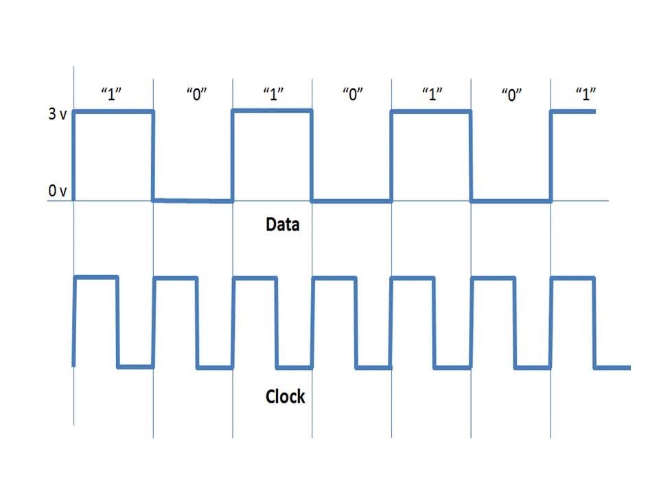
Figure 1. Data bits where logical “0” and “1” are represented by 0 volts and 3 volts respectively
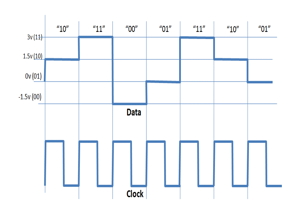
Figure 2. Notional encoding. Four signaling levels per clock cycle can represent two data bits.
But what if we design a system so that a single electrical symbol can take on more than two levels? In figure 2, we see that each symbol can now take on one of four voltages (-1.5v, 0v, +1.5v, +3v). Since M=4, our line code can now represent four binary states: -1.5v = "00", 0v="01", +1.5v="10", +3v="11". So for every one symbol we send, we actually send 2 bits of information. In other words, using the same Baud rate and by adopting four possible values per symbol, we've essentially doubled our data rate throughput!
Hartley's law gives us a handy formula for determining the relationship between symbol rate (baud) and data rate (bps). This equation is:
R (bps) = S (baud) x log2M, where “R” represents the data rate (bps), “S” represents the symbol rate (baud), and “M” equals the number of signaling levels per clock cycle.
Using Hartley’s equation for our first example (figure 1), we find
R = S x log22, where M=2 (0v or 3v)
Since log22=1, we find that R = S. In other words, symbol rate given in baud equals data rate given in bits per second. log2M gives us the number of bits that can be represented by a single symbol. In this case log2M= log22=1 bit.
Now let’s look at our situation in figure 2 where we are allowed to have several voltage levels per symbol for each clock cycle. We see that a symbol can take on one of four voltage levels (M=4) per clock pulse. As such, two data bits can be sent per symbol.
M(signaling levels) = 2N(Bits); if M=4, then N=2 bits
Applying Hartley we find that,
R(bps) = S(baud) x log2(4) = S x 2
which states that the data rate transmitted is two times the rate of the symbols passed. As such, two times more data can be transmitted per this scheme compared to the previous figure 1 example.
From the examples above, we see that symbol rate (baud) differs from data rate (bps) although these two values may be equal depending upon line coding or modulation schemes. Through Hartley’s Law, we can determine the relationship between baud and data rate as long as we know the number of signaling levels (or states) that a symbol can have.