Dr. Riki Morikawa, George Mason University
Balanced Versus Unbalanced Guided Media
Back to Index
Both balanced (e.g., 2-wire and 4-wire) and unbalanced (e.g., coaxial cables) guided media are used prevalently in today’s telecommunications systems. So what do these terms actually mean? …and why are they important for telecommunications?
The answers to these questions reside in how each handles noise. As we know, electromagnetic (EM) noise from numerous sources in the environment will degrade signal quality, sometimes to the point where the distant end receiver cannot distinguish the signal from the noise itself. The signal to noise ratio (SNR) is an important measure that helps determine whether a signal can be reliably received. The signal-to-noise ratio in decibels is given by the formula:
SNR(dB) = 10 log10[(signal power)/(noise power)]
From the above equation, it can be seen that as RF noise increases, SNR decreases, and reception eventually degrades to nothing. By reducing or eliminating EM noise from the signal’s environment, our ability to receive signals reliably and at greater distance improves.
Balanced and unbalanced circuits handle this noise problem in different ways. To illustrate, consider a simple 2-wire “unbalanced” guided medium system similar to the one that existed in the early days of the telegraph. One wire (or conductor) carried the signal while the second conductor provided a common reference point or ground for the circuit. Fig. 1 illustrates an unbalanced 2-wire transmission system in a RF “noise-free” environment. We use a simple sine wave to represent the signal being transmitted from point “A” to point “B”.

Figure 1. Unbalanced 2-wire circuit in a noise-free environment.
In a noise free environment, the signal is not degraded[1] by RF noise within the environment of the telecommunications lines.
Now let’s introduce a simple discrete noise source[2] that is the same frequency as the signal, but with different amplitudes and phase angles.
Signal: s(t) = 4 sin (2pft)
Noise: n(t) = 2 sin (2pft + 90o)
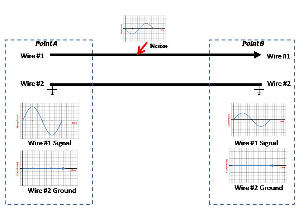
Figure 2. Noise Introduced to a 2-wire unbalanced circuit.
We see that in the unbalanced case when no EM shielding[3] exists, the noise element adds detrimentally to the signal element resulting in a lower signal received or SNR at the point B receiver.
The coaxial cable is an example of an unbalanced guided medium in which the center signal conductor is protected by an outer layer shield connected to ground. Fig. 3 shows how noise current is shunted harmlessly to ground. In this case, the signal is not degraded due to noise.
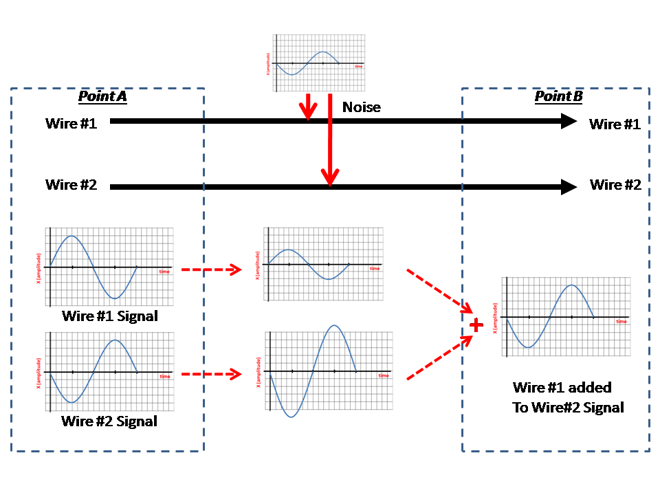
Figure 3. Coaxial Cable. RF Noise is intercepted by the Coax’s outer shield and shunted to ground.
In contrast, balanced guided media handles noise in a very different manner. With balanced media, the signal is transmitted over two conductors, however each signal is essentially the mirror image of the other (i.e., both signals are polar opposites). Because EM noise tends to be of a single polarity, it affects the signal on each conductor differently. The differences between the two received signals can then be combined to eliminate the noise element, thus recovering the original signal transmitted (fig. 4).

Figure 4. Balanced Media results in noise cancellation.
Four-wire media is typically used for full-duplex data communications. Like 2-wire, 4-wire is balanced with two conductors used for transmit data, and the other two conductors used for receive data.
[1] The signal will still experience attenuation which is dependent upon the distance between points A and B, and the frequency used. These factors, while significant in determining signal quality, are not discussed in this lesson.
[2] Noise sources are complex and therefore cover a frequency bandwidth vice a discrete frequency. For this specific explanation, however, we choose a very simple “pure” or discrete frequency noise source to simplify the description.
[3] The “shielding” is made of conductive material that is wrapped around the signal conductor, separated from one another via non-conductive material. The shield is connected to an electrical ground, effectively shunting any noise current harmlessly to ground and away from the signal itself.