| Daniel Jacobson's MATH 447 Webpage | Class Page | ||||||||||||||
|---|---|---|---|---|---|---|---|---|---|---|---|---|---|---|---|
|
Home
≫
Project 4
≫
Part A: Cooling Fin
Project 4: Partial Differential Equations Daniel Jacobson and Zakaria Zerhouni | |||||||||||||||
|
This project simulates the heat distribution across a cooling fin. Heat is applied to the fin along the left edge, distributed throughout the system by conduction, and lost along the surface and edges by convection, as shown below. 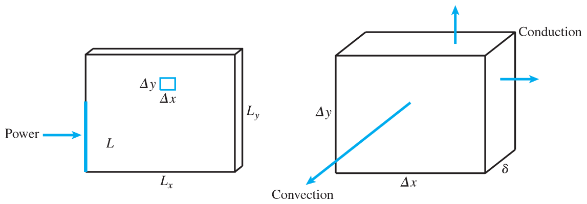
Let \(P\) (in watts) be the total power, applied uniformly across an \(L\) cm segment of the left side. Let \(\delta\) (in cm) be the thickness of the fin, let \(K\) be the thermal conductivity of the fin material (in W/cm°C), and let \(H\) be the convective heat transfer coefficient of the surrounding medium (in W/cm²°C). \(u(x,y)\) represents the difference between the temperature of a point on the fin and the surrounding background temperature, \(u_b = 20^{\circ} \text{C}\). On the interior points, heat is transfered through along the four interior faces by conduction, governed by Fourier's first law \(q = - K A \nabla u\), and through the two exterior faces by convection, governed by Newton's law \(q = - H A u\), leading to the steady state solution \(u_{xx}+u_{yy}=\frac{2H}{K\delta}u\), approximated by the finite difference equation \[ \frac{u_{i+1,j}-2u_{ij}+u_{i-1,j}}{\Delta x^2} + \frac{u_{i,j+1}-2u_{ij}+u_{i,j-1}}{\Delta y^2} = \frac{2H}{K\delta}u_{ij}\] Heat input is described by the Robin steady-state boundary condition \( u_{norm} = \frac{P}{L \delta K} \) across the relevant section of the left side of the fin, approximated by the finite difference equation \[ \frac{-3u_{1j} + 4u_{2j} -u_{3j}}{2 \Delta x} = - \frac{P}{L \delta K} \] The remainder of the edges lose heat through convection, once again governed by Newton's Law, resulting in the steady-state boundary condition \( u_{norm} = - \frac{H}{K}u \), which on the bottom edge takes the form \[ \frac{-3u_{i1}+4u_{i2}-u_{i3}}{2 \Delta y} = \frac{H}{K}u_{i1} \] The coolingfin method code used to solve the following problems can be found here.
Problem 1: Temperature across a 2 × 2 cm fin (1mm thick) with 5W applied across entire left side
(M = N = 10 steps, maximum temperature 146 °C): 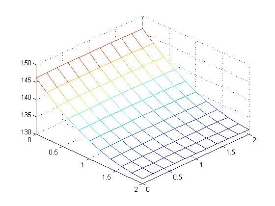
Problem 2: Temperature across a 4 × 4 cm fin (1mm thick) with 5W applied across lower 2cm of left
side, at multiple values of M and N. (from top left: M = N = 10, 20, 40, 80, 160, and 320 steps) 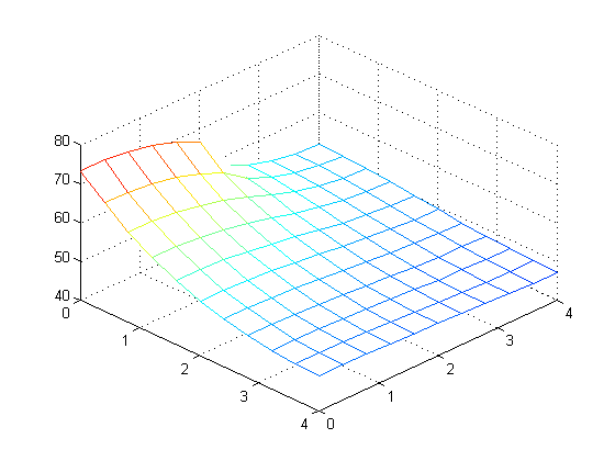
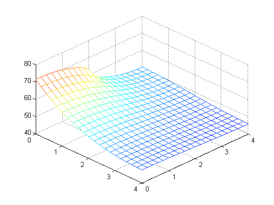
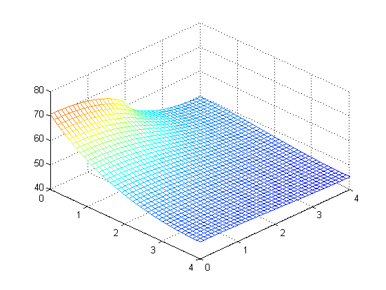
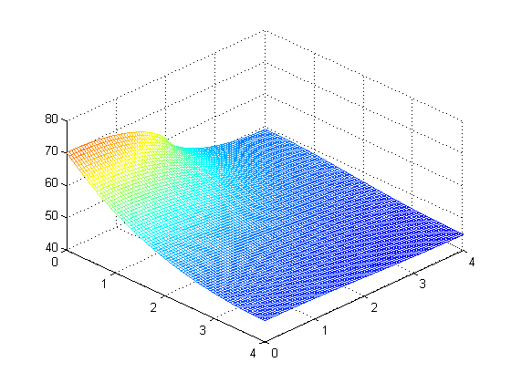
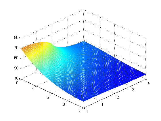
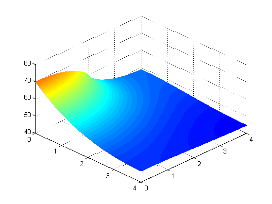
Calculated maximum temperature at different values of M and N: 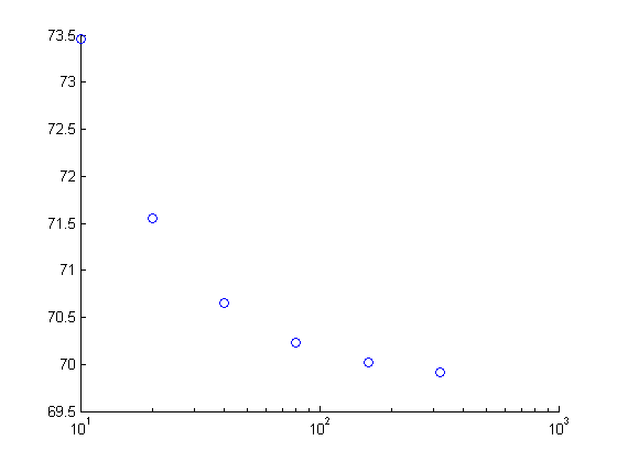
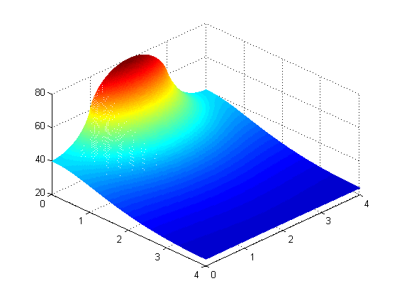
Problem 3: Maximum power the same fin can support while remaining below 80 °C,
applied at edge (max 6.0W) and middle (max 6.6W) 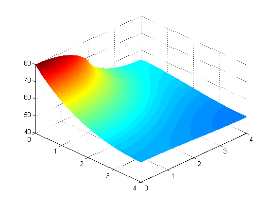
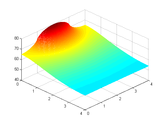
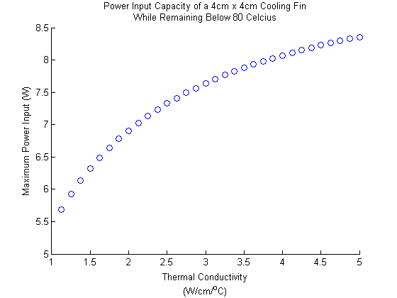
Problem 4: Using the optimal middle placement from problem 3, but with a copper fin
(K = 3.85 instead of 1.68, greater heat capacity allows fin to support up to 8.1W) 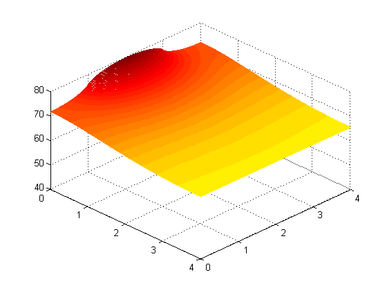
| |||||||||||||||
| |||||||||||||||
